The default settings leave AutoCAD in “maximum attempt at being helpful” mode. That is, AutoCAD moves the text, dimension lines, and arrows around automatically so that nothing overlaps. On rare occasions, AutoCAD’s guesses might be less than perfect.
- After you create your first dimension, AutoCAD creates a new layer called 'DEFPOINTS'. This is used only for the small points you see at the end of an extension line. This layer will not print - so be sure not to draw on it. Keep even spacing between you dimensions and between your dimension and your object lines.
- Learn AutoCAD hotkeys and commands with the AutoCAD Shortcut Keyboard guide to help you work faster and be more efficient while using AutoCAD software.
- You should leave Use for set to All dimensions unless you want to explicitly create a sub style for specific dimension types. You will learn more about sub styles later in this document. When you pick Continue you are prompted to modify dimension variable settings and these settings are arranged on logical tabs.
A dimension style (or dimstyle, for short) is a collection of drawing settings, called dimension variables (or dimvars, for short) in AutoCAD 2014 , which are a special class of the system variables.
If you do need to create your own dimension styles or you want to tweak existing ones, use the DIMSTYle command. You can invoke it by clicking the small, diagonal arrow in the lower-right corner of the Dimensions panel of the Annotate tab on the Ribbon. The Dimension Style Manager dialog box opens.

Every drawing comes with a default dimension style named Standard (for imperial [feet-and-inches] drawings) or ISO-25 (for metric drawings) and a matching annotative style. Although you can use and modify the Standard or ISO-25 style, you are encouraged to leave them as is and create your own dimension style(s) for the settings that are appropriate to your work.

This approach ensures that you can use the default style as a reference. More important, it avoids a potential naming conflict that can change the way your dimensions look if the current drawing is inserted into another drawing.
When you install AutoCAD, it checks with the operating system (OS) to see what country was selected when the OS was installed, and then sets its measurement system accordingly. If you’re in the United States or one of the few other countries that still use imperial units, the default dimension style is Standard; most of the rest of the world defaults to ISO-25.
The system variable MEASUREINIT controls the default action. If set to 0 (zero), AutoCAD uses imperial units; if set to 1, metric units are used. Among other things, this setting also affects text styles, hatching, and noncontinuous line types.
Starting a new drawing from an ISO template (for example, acadiso.dwt) forces everything to metric, and starting a new drawing from a non-ISO template (for example, acad.dwt) forces everything to imperial, regardless of the setting of MEASUREINIT.
The system variable MEASUREMENT overrides the default for a specific drawing, but it affects only text, hatching, and noncontinuous line types.
Follow these steps to create your own dimension style(s):
Autocad Dimension Settings
On the Ribbon’s Home tab, click the label of the Annotation panel to open the panel slideout, and then click the Dimension Style button.
Alternatively, if that just sounds like too much work, you can type D and press Enter. The Dimension Style Manager dialog box appears.
In the Styles list, select the existing dimension style whose settings you want to use as the starting point for the settings of the new style.
For example, select the default dimension style named Standard or ISO-25.
Click the New button to create a new dimension style that’s a copy of the existing style.
The Create New Dimension Style dialog box appears.
Enter a New Style Name and then select or deselect the Annotative check box. Click Continue.
Select the Annotative check box to create an annotative dimension style, or deselect it for a non-annotative style.
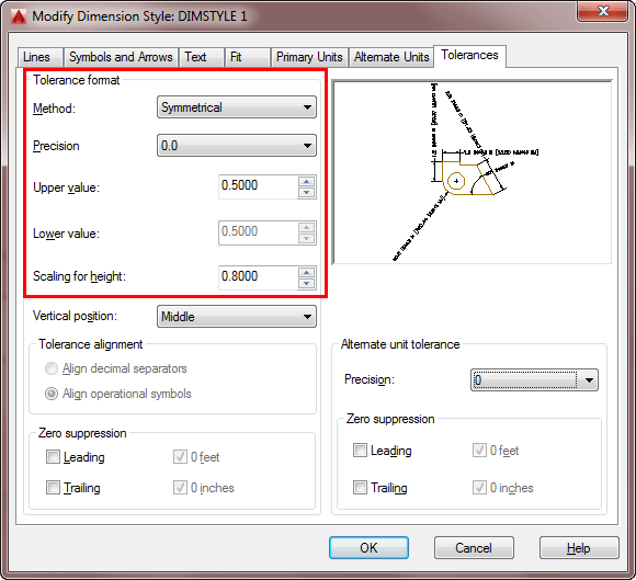
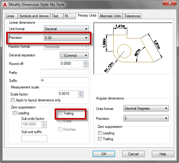
The New Dimension Style dialog box appears. (This dialog box is virtually identical to the Modify Dimension Style dialog box, which is displayed when you edit a dimension style.)
Modify dimension settings on any of the seven tabs in the New Dimension Style dialog box.
Click OK to close the New Dimension Style dialog box.
The Dimension Style Manager dialog box reappears.
Click Close.
The Dimension Style Manager dialog box closes, and the new dimension style becomes the current dimension style that AutoCAD uses for future dimensions in this drawing.
Draw dimensions to test the new dimension style.
Avoid changing existing dimension styles that you didn’t create, unless you know for sure what they’re used for. When you change a dimension style setting, all existing dimensions using that style change to reflect the revised setting.
Thus, one small dimension variable setting change can affect a large number of existing dimensions! To play it safe, rather than modify an existing dimension style, create a new style by copying an existing one and modifying the new one.
Autocad Dimension Style Settings
A further variation on the already convoluted dimension styles picture is that you can create dimension substyles (also called style families), which are variations of a main style that affect only a particular type of dimension, such as radial or angular. If you open the Dimension Style Manager dialog box and see names of dimension types indented beneath the main dimension style names, be aware that you’re dealing with substyles.